 |
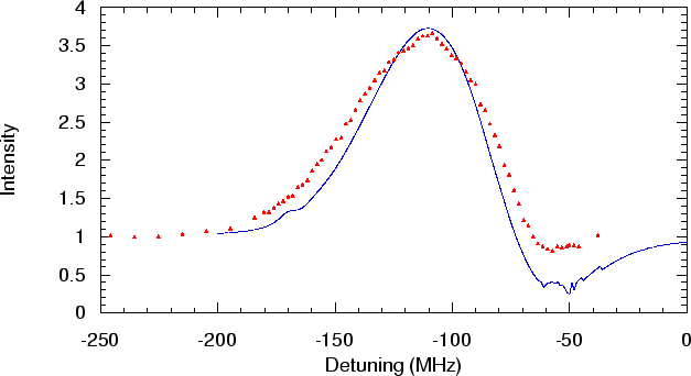
In the next experiment, we will examine the behavior of the collimator with different detunings of the collimator laser. We lock the MOC laser exactly on resonance, and use the beat signal of the MOC laser and the collimator laser to adjust the detuning of the collimator laser. The channeltron is put on the center line of the setup. The detuning of the collimator laser can now be adjusted over a wide range, as has been described in sec. 2.7.2. In fig. 3.2 the dependency of the channeltron signal with respect to the detuning of the collimator laser can be seen.
 |
The line in fig 3.2 is the simulated detuning
dependency of the collimator. In the simulation we chose
![]() mrad,
mrad, ![]() and
and ![]() m/s, close to the
values in the experimental situation. The
velocity spread in the simulation is 300 m/s, which is smaller
than the
value of 378 m/s that we found with the TOF measurement.
Another difference between the simulation and the experiment is
that in the simulation, all atoms are He* atoms, while in the
experiment the channeltron also detects (
m/s, close to the
values in the experimental situation. The
velocity spread in the simulation is 300 m/s, which is smaller
than the
value of 378 m/s that we found with the TOF measurement.
Another difference between the simulation and the experiment is
that in the simulation, all atoms are He* atoms, while in the
experiment the channeltron also detects (![]() S) He atoms and
photons. We corrected for this by checking the percentage of He* atoms
during the experiment.
S) He atoms and
photons. We corrected for this by checking the percentage of He* atoms
during the experiment.
The simulated and measured data match quite well, the maximum gain is for both the simulation and the experiment at a detuning of -113 MHz. The width of the peak is almost the same for both experiment and simulation, although the simulated signal has a smaller width. This can be explained by the fact that the velocity spread in the simulation is a bit smaller than the velocity spread of 378 m/s found in sec. 3.4. Another difference is that there is a larger dip in the signal at a detuning of -50 MHz. At this detuning the laser beam at the end of the collimator laser is more in resonance with the atoms having already a velocity component in the direction of that laser beam, and the atoms are pushed away from the center line of the setup.
The points measured in fig 3.2 have a spread in frequency of about 3 MHz, since the laser stabilization making use of the beat signal is not more accurate than 3 MHz. The experimental data for detunings smaller than -40 MHz could not be done with the laser stabilization using a beat signal, since the stabilization unit gets unstable at detunings smaller than 40 MHz, the variation of the frequency became in the order of 10 MHz for detunings less than 40 MHz to the red.