 |
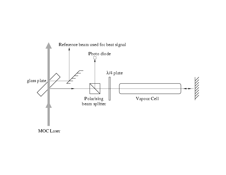
To reduce the variation in frequency of the laser light for the Magneto-Optical Compressor we used the method of saturation spectroscopy to stabilize the laser. The setup of this technique is shown in fig 2.8.
A small part of the laser beam is split off by a glass plate, and goes through a polarizing beam splitter. The laser light that passed the polarizing beam splitter is linearly polarized, and becomes circularly polarized by the
The vapor cell is filled with He atoms at room temperature, under a
pressure of 0.08 mbar, excited to the metastable state by an rf-field.
The light will pass
the vapor cell, is then retro-reflected at the mirror, and will pass the
vapor
cell and the ![]() /4-plate again. The polarization of the laser beam
has turned 90 degrees after passing the polarizing beam splitter for
the first time, and it will now be reflected on the photo diode, which
measures the intensity of the laser beam.
If the laser light is slightly under resonance, the atoms which have a
velocity
/4-plate again. The polarization of the laser beam
has turned 90 degrees after passing the polarizing beam splitter for
the first time, and it will now be reflected on the photo diode, which
measures the intensity of the laser beam.
If the laser light is slightly under resonance, the atoms which have a
velocity ![]() that satisfies
that satisfies
![]() will
be in resonance with the laser. Since the laser shines through the vapor
cell in two directions opposite to each other, there will be two classes
of velocities that absorb the photons. The intensity of the laser
beam will decrease.
will
be in resonance with the laser. Since the laser shines through the vapor
cell in two directions opposite to each other, there will be two classes
of velocities that absorb the photons. The intensity of the laser
beam will decrease.
If the laser is exactly on resonance, that is
![]() , both the laser
beams are in resonance with the same velocity class (
, both the laser
beams are in resonance with the same velocity class (
![]() ). Since the
first laser beam has already excited He* atoms to the
). Since the
first laser beam has already excited He* atoms to the ![]() state, the second
laser beam will be absorbed much less.
This results in a small peak of increased intensity in the
transmission signal when the laser is
exactly on resonance.
This peak is called the Lamb dip.
state, the second
laser beam will be absorbed much less.
This results in a small peak of increased intensity in the
transmission signal when the laser is
exactly on resonance.
This peak is called the Lamb dip.
We now add a sine shaped current with an amplitude so small that it alters the frequency of the laser only a few MHz (the current used for fig 2.9 was big enough to show both the D2 and the D1 line, which are separated by 2.299 GHz), and with a frequency of 2 KHz. If the laser is on resonance, the sine shaped current will make the laser scan over the top of the Lamb dip [7]. By integrating the signal received from the diode, multiplied by a square wave voltage with exactly the same frequency as the sine, it can be seen if the laser is exactly on top of the Lamb dip, or on one of the flanks. If the laser is exactly on resonance, the first part of the integral gives a positive value due to the square wave, and the second part gives the same, but negative value. The total sum will be zero, and no correction has to be made to the laser frequency.
If the laser frequency is slightly under resonance, the Lamb dip peak will fall in the first part of the integral, and the total sum will be positive. A frequency slightly above resonance will result in a negative sum. We use this positive or negative value to correct the frequency of the laser. This method of stabilizing the frequency is very effective, only when the laser frequency changes so fast that the Lamb dip can not be seen within the amplitude of the scan signal, the laser can get unlocked, but under normal circumstances the laser could be locked on resonance for hours.
The lasers that we use need to have a frequency that is slightly
detuned to the red from resonance. The method of locking the laser
frequency as described above can still be used, but to compensate for the
change in frequency, we must add a magnetic field over the vapor cell.
Since we use ![]() light, the used transition will be the transition
from the He(
light, the used transition will be the transition
from the He(![]() S
S![]() , m=1) to the He(
, m=1) to the He(![]() P
P![]() , m=2) state. The change
in energy separation between these two states caused by the applied
magnetic field can be calculated with use of equation
1.6, and is found
to be:
, m=2) state. The change
in energy separation between these two states caused by the applied
magnetic field can be calculated with use of equation
1.6, and is found
to be: