


Next: Lasers and optics
Up: The collimator
Previous: Preparing the angles of
Contents
Aligning the collimator
When the angles  and
and  are adjusted to the correct
values, the collimator is placed in the vacuum chamber behind the He*
source. The collimator creates a beam of He* atoms parallel to the central
axis of the collimator. So it is important that this central axis and the
beam line from the He* source to the channeltron coincide.
One end of the collimator can be moved in horizontal en vertical direction with
the use of adjustment screws. To align the collimator we used the setup
shown in fig
2.6.
are adjusted to the correct
values, the collimator is placed in the vacuum chamber behind the He*
source. The collimator creates a beam of He* atoms parallel to the central
axis of the collimator. So it is important that this central axis and the
beam line from the He* source to the channeltron coincide.
One end of the collimator can be moved in horizontal en vertical direction with
the use of adjustment screws. To align the collimator we used the setup
shown in fig
2.6.
Figure 2.6:
Decreasing the angle  between the collimator axis and the beam
axis.
between the collimator axis and the beam
axis.
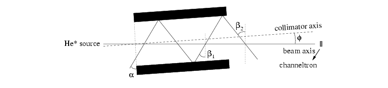 |
The laser light is shone in from one side under a large angle  with the collimator axis, so that the number of reflections inside the
collimator is small. If the collimator axis is misaligned by an angle
, the light coming from one side
of the collimator makes an angle
with the collimator axis, so that the number of reflections inside the
collimator is small. If the collimator axis is misaligned by an angle
, the light coming from one side
of the collimator makes an angle
 with the beam axis and
the light coming from the other side of the collimator makes an angle
with the beam axis and
the light coming from the other side of the collimator makes an angle
 with the beam axis.
Since the angles with the beam axis are not the same, the detuning for which the
laser light would optimally deflect the He* atoms from the beam axis is
not the same for the two sides. We periodically changed the frequency of
the laser light
around resonance, by putting a current with a sawtooth shape on the laser
diode.
If the detuning is optimal for one of the two angles to interact with the
He* atoms, the number of atoms detected at the channeltron will drop
significantly. If we scan over the frequency and the angle is not
zero, we will see two dips in the signal.
with the beam axis.
Since the angles with the beam axis are not the same, the detuning for which the
laser light would optimally deflect the He* atoms from the beam axis is
not the same for the two sides. We periodically changed the frequency of
the laser light
around resonance, by putting a current with a sawtooth shape on the laser
diode.
If the detuning is optimal for one of the two angles to interact with the
He* atoms, the number of atoms detected at the channeltron will drop
significantly. If we scan over the frequency and the angle is not
zero, we will see two dips in the signal.
Figure 2.7:
Channeltron signal with sawtooth current on diode laser,
with large angle (above) and small angle (below).
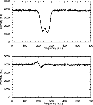 |
The distance between these dips is an indication of the angle . If
the angle is zero, the two angles  and
and  are
equal, and instead of two dips, we will see only one, much smaller dip.
The dip will be smaller since the atoms are now in resonance with the laser
light coming from both mirrors at the same time. Since the laser light
leaves the collimator at the same side as it enters the collimator, we
know that the number of times the laser light overlaps the He* beam is
even, so that the number of times the laser light interacts with the beam
from one side is equal to the number of times the laser light interacts
with the beam from the other side. This means that when the angle
is zero, the two forces on the He* atoms are almost equal and opposite,
and the net force on the He* atoms is almost zero.
are
equal, and instead of two dips, we will see only one, much smaller dip.
The dip will be smaller since the atoms are now in resonance with the laser
light coming from both mirrors at the same time. Since the laser light
leaves the collimator at the same side as it enters the collimator, we
know that the number of times the laser light overlaps the He* beam is
even, so that the number of times the laser light interacts with the beam
from one side is equal to the number of times the laser light interacts
with the beam from the other side. This means that when the angle
is zero, the two forces on the He* atoms are almost equal and opposite,
and the net force on the He* atoms is almost zero.
The width of the dip is not only caused by the width of the
transition given by equation 1.4, but
is mainly caused by the velocity distribution of the He* source. Since the
channeltron is placed at a distance of 4.5 meters behind the collimator,
the spread in the velocity of 350 m/s will cause a spread in flight time
of 1.3 ms. The signal received at the channeltron is a convolution of the
resonant frequency range of the laser and the time distribution. This
makes it more difficult to find the correct position of the collimator for
which the angle is zero. When the angle is minimized as well
as can be done with this method, we shine the lasers in from both sides
under the angle  and optimize the angles
 and
and
 for the two pairs of mirrors independently until the
channeltron signal is optimal.
for the two pairs of mirrors independently until the
channeltron signal is optimal.
Next: Lasers and optics
Up: The collimator
Previous: Preparing the angles of
Contents
Vincent van der Bilt
2002-12-27